PLCs and IEC 61131-3: How Software Controls Machinery
How a PLC works: scan cycle, I/O images, Ladder, Structured Text, FBD, SFC, and IL in IEC 61131-3, with line-by-line examples and software engineering contrasts.

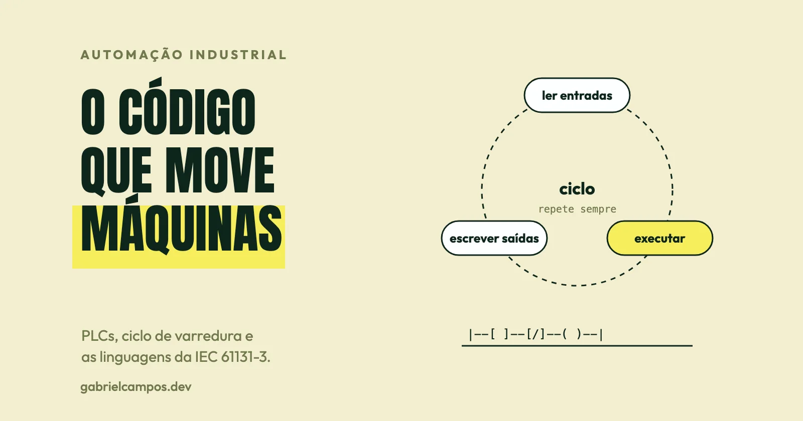
In the previous article, the programmable logic controller (PLC) appeared at the core of the machine control layer: reading physical sensors, evaluating logical conditions, and driving field actuators. Here, we open that black box. How does an industrial controller actually execute code? Why does plant automation rely on specialized programming languages? And how does software engineering change when your program drives a 500-ton hydraulic press instead of returning a JSON response?
What is a PLC
A PLC (Programmable Logic Controller) is a ruggedized industrial computing platform engineered to control physical processes deterministically and continuously. It features a microprocessing CPU, system memory, physical input and output modules (or deterministic remote I/O via industrial networks), and a specialized runtime kernel that iterates through control logic indefinitely.
The IEC 61131 series governs programmable controllers. Its third part, IEC 61131-3, defines the syntax and semantics for a unified suite of industrial programming languages. The initial edition dates to the early 1990s; the third edition was published in 2013 and, according to IEC catalog records, was superseded in May 2025 by a new fourth edition. The IEC catalog notes describe the 2013 edition as a backwards-compatible technical revision that introduced extended data types, type conversion functions, explicit references, namespaces, and object-oriented features for classes and function blocks.
Two essential framing principles:
- IEC 61131-3 standardizes programming languages and software architectures, not hardware backplanes or fieldbus communication protocols. Protocols such as PROFINET or EtherNet/IP operate independently (explored in article 06).
- Compliance is partial and vendor-dependent. Every industrial automation vendor implements the standard with proprietary dialect extensions and omissions. Control code written for one manufacturer’s IDE rarely compiles on another without substantial refactoring.
Inside the PLC: inputs, outputs, and the scan cycle
The foundational execution paradigm of a classic PLC is the scan cycle, executing continuously in an unbroken loop:
- Input scan. Physical digital and analog input modules are sampled, and their states are copied into an internal memory buffer called the process image input (PII).
- Logic execution. The user application evaluates logic against this snapshot in memory, rather than querying hardware terminals directly.
- Output write. Computed states are copied from the process image output (PIQ) to physical output modules.
- Housekeeping tasks (network communication, background diagnostics), varying according to CPU architecture.
The Siemens S7-1500 system manual on cycle and reaction times details this exact sequence: during each cyclic pass, process input and output images update before cyclic organization blocks (such as OB1) execute. The manual highlights a critical distinction: cycle time is only a component of total reaction time, which spans the moment a physical input signal transitions to the physical reaction at an output terminal. A sensor transitioning midway through a scan cycle will only be evaluated in the subsequent cycle.
Why use a buffered process image? To guarantee that throughout a single execution pass of the control routine, each input retains a strictly consistent value. Without an atomic image snapshot, two rungs within the same scan could read contradictory values from a bouncing sensor, producing erratic behavior.
IEC 61131-3 adds hierarchical organization: a hardware resource (a processing CPU) hosts multiple concurrent tasks, each bound to programs scheduled periodically or triggered by hardware interrupts. This multitasking enables a single controller to run a high-priority 1 ms motion interpolator alongside a low-priority 50 ms sequential packaging routine. Specific nomenclature (such as Organization Blocks in Siemens or Task Priorities in Rockwell) reflects vendor implementations.
Physical inputs and outputs
- Digital (discrete): two binary states (0 or 1). Examples: optical presence sensors (input), motor contactors (output).
- Analog: continuous voltage or current levels, digitized into raw signed integers by analog-to-digital converters (e.g., 4–20 mA current loops, 0–10 V signals). The control code must scale this raw integer into physical engineering units (bar, °C, mm/s) and validate against wire-break failure states.
- Specialized / complex: high-speed encoder counters, PWM pulse trains, serial communication cards. These rely on specialized coprocessors.
The five IEC 61131-3 programming languages
The standard defines both graphical and textual languages that interoperate seamlessly within a shared project architecture, referencing common data structures and function blocks.
Ladder Diagram (LD). A graphical language styled after electromechanical relay wiring diagrams. Logic is arranged in parallel “rungs” between two vertical power rails. It remains the most widely deployed language across discrete manufacturing because it is immediately intuitive to electrical engineers and plant maintenance technicians.
Function Block Diagram (FBD). A graphical data-flow language where algorithmic blocks connect via directional signal lines, mirroring electronic schematic diagrams. Widely preferred in continuous process control loops (PID), mathematical calculations, and analog signal conditioning.
Structured Text (ST). A high-level, block-structured textual language derived from Pascal. It is the language most familiar to general software developers: formal variable declarations, loops (FOR, WHILE), conditionals (IF-THEN-ELSE, CASE), and modular functions. Well suited for algorithmic calculations, complex data manipulation, and dense state logic.
Sequential Function Chart (SFC). A graphical language derived from Petri nets that structures programs into discrete steps (states) and conditional transitions, supporting parallel operational branches. It is the natural choice for sequential batch processes, recipe sequencing, and machine operating state machines.
Instruction List (IL). A low-level textual language resembling machine assembly. It was formally deprecated in the third edition (2013) and, according to literature, removed in the fourth edition (2025). It still lingers in legacy installations, with select vendors maintaining compilation backwards compatibility. For greenfield systems, it should not be used.
Language selection matrix
| Language | Paradigm | Common use cases | Core advantage | Inherent limitation |
|---|---|---|---|---|
| LD | Graphical | Interlocks, discrete sequences, field troubleshooting | Intuitive for electrical technicians | Scales poorly for complex mathematics |
| FBD | Graphical | Closed-loop PID, analog conditioning | Clear visual signal flow | Large diagrams become visually tangled |
| ST | Textual | Complex algorithms, string handling, data arrays | Expressive, Git-diffable, maintainable | Less accessible to purely electrical staff |
| SFC | Graphical | State machines, batch phases, sequence coordination | States and active paths visually obvious | Requires disciplined state modeling |
| IL | Textual | Legacy brownfield codebases | Compact memory footprint | Deprecated and discontinued |
In practice, engineering teams blend them: SFC or ST for macro sequence coordination, Ladder Diagram for safety-interlock rungs that maintenance teams must monitor online, FBD for analog control loops, and ST for data handling. This reflects established industry engineering practice rather than a rigid normative mandate, and conventions vary by geography and vendor.
Example 1: Motor start/stop with seal-in circuit in Ladder
The classic motor circuit utilizes a seal-in (latch) topology: a momentary push button starts the motor, and an auxiliary contact on the motor’s own output maintains the energized circuit until a stop button or thermal overload breaks the circuit. An illustrative text representation:
|     Start        Stop      Overload       Motor    |
|--+---[ ]----+----[/]--------[/]-----------( )------|
|  |          |                                      |
|  |  Motor   |                                      |
|  +---[ ]----+                                      |
The Motor contact is wired in parallel with Start: either input can supply power to the rest of the rung.
Component-by-component breakdown:
[ ]is a normally open contact: conducts logical continuity when its associated boolean tag is 1.[/]is a normally closed contact: conducts logical continuity when its associated boolean tag is 0.( )is an output coil: sets its target memory bit to 1 when power flows across the entire rung.Start: momentary start push button (digital input). When pressed, it evaluates to TRUE.Motor(parallel contact): reads the current state of the output coil. Once energized, this contact closes, maintaining rung continuity even after the operator releases theStartbutton. This is the seal-in.Stop: normally closed contact. As long as the button is unpressed, its electrical bit is 0, allowing continuity. Pressing the button breaks rung continuity immediately.Overload: thermal overload relay contact, also wired normally closed, interrupting the rung if the motor draws excessive current.Motor(coil): physical output driving the electromagnetic motor contactor.
An essential engineering design principle: stop buttons and thermal overloads are physically wired in the field as normally closed (NC) circuits. If a physical field wire breaks or a terminal disconnects, the input drops to 0, which the PLC interprets as an immediate stop request rather than running unchecked. This is fundamental fail-safe wiring design. True machine safety functions (emergency stops, light curtains) must conform to dedicated safety standards (ISO 13849 / IEC 62061) and utilize dedicated functional safety PLCs; this example is not a certified safety circuit.
During cyclic execution, this rung is evaluated every single scan. If Start is held high, the PLC energizes Motor in the process output image on that pass, driving the physical contactor at the end of the scan.
Example 2: Tank level control in Structured Text
The following snippet is an illustrative implementation conforming to IEC 61131-3 principles (not compiled in a specific vendor IDE). It regulates a tank fill pump featuring level hysteresis, dry-run protection, and latched fault reset logic.
PROGRAM FillTank
VAR
    LowLevel    AT %IX0.0 : BOOL;  // low-level sensor (TRUE = liquid covers sensor)
    HighLevel   AT %IX0.1 : BOOL;  // high-level sensor
    FlowOk      AT %IX0.2 : BOOL;  // flow switch at pump discharge
    Reset       AT %IX0.3 : BOOL;  // fault reset button
    Pump        AT %QX0.0 : BOOL;  // output to motor contactor

    PumpFault   : BOOL;
    DryRunTimer : TON;             // timer on-delay
END_VAR

// 1. Level hysteresis
IF NOT PumpFault THEN
    IF NOT LowLevel THEN
        Pump := TRUE;              // level below minimum: start pump
    ELSIF HighLevel THEN
        Pump := FALSE;             // reached maximum: stop pump
    END_IF;
ELSE
    Pump := FALSE;                 // never run during fault
END_IF;

// 2. Dry-run protection
DryRunTimer(IN := Pump AND NOT FlowOk, PT := T#5S);
IF DryRunTimer.Q THEN
    PumpFault := TRUE;
END_IF;

// 3. Manual fault reset
IF Reset THEN
    PumpFault := FALSE;
END_IF;
END_PROGRAM
Line-by-line breakdown:
AT %IX0.0declarations map symbolic variable identifiers directly to hardware I/O addresses (%Iindicates inputs,%Qoutputs,Xsingle-bit width). In modern production codebases, this binding is typically abstracted into vendor hardware configuration tables.- Section 1 (hysteresis). In the absence of an active fault: if the liquid level drops below the bottom sensor (
NOT LowLevel), the pump engages. Once liquid hits the upper sensor (HighLevel), it disengages. While liquid fluctuates between the two probes, neither condition evaluates to true, andPumpretains its previous value. This hysteresis prevents rapid cycling (chattering) of the contactor. This behavior works specifically because the code executes cyclically and internal variable states persist across scans. - Section 2 (dry-run protection).
TONis the standard IEC on-delay timer block. Its accumulator increments only whileINis high—that is, while the pump output is energized and the discharge flow switch reports no flow. If this dry condition persists for 5 contiguous seconds (T#5S, the standard time literal),DryRunTimer.Qasserts TRUE, latchingPumpFault. BecausePumpFaultis an internal boolean variable cleared only by operator intervention, the fault condition remains latched. - Section 3 (manual reset). Clears the latched fault when an operator presses the physical reset button. Because this line follows Section 2, during a cycle where both evaluate true, the reset clears the fault. In this specific program this introduces no race condition because the pump was deactivated on the fault scan and the timer resets. In complex industrial applications, statement execution sequence within the cyclic scan requires careful architectural design.
Notice that execution sequence is strictly sequential: unlike an asynchronous event-driven system, runtime state transitions depend directly on instruction ordering within the scan.
Machine states, fault handling, and diagnostic logging
A substantial portion of industrial PLC logic handles abnormal physical conditions rather than nominal operation: jammed mechanical tooling, failed optical sensors, emergency interruptions, power blips, and transitions between manual and automatic modes. Established engineering patterns include:
- Formalizing equipment control around explicit finite state machines (such as PackML: Stopped, Starting, Idle, Running, Holding, Aborting) rather than sprawling nested boolean conditionals.
- Defining the deterministic fail-safe state for every physical output if fieldbus communications drop or a CPU fault occurs.
- Completely decoupling manual jog modes from automatic cycle modes, enforced by rigid software interlocks.
- Utilizing retentive memory (
RETAINqualifiers defined by the standard) selectively, designating which process counters and batch parameters must survive a power outage. - Generating structured diagnostic payloads: machine alarm codes, cycle counters, and event timestamps that upper-tier SCADA and MES systems can ingest.
Controllers also enforce a hardware/software scan cycle watchdog: if user logic exceeds a configured execution ceiling (e.g., 100 ms) due to an infinite loop, the CPU immediately halts into a safe fault condition.
Determinism versus general software development
This is where classical software developers encounter the starkest paradigm shift:
Continuous, deterministic cyclic execution. A PLC does not wait on external asynchronous request loops: it runs its programmed scan loop endlessly, where scan duration is a foundational engineering constraint. For physical control systems, what matters is that execution latency is bounded, repeatable, and deterministic, rather than achieving raw peak speeds with high jitter.
Static allocation and no unhandled exceptions. The language standard discourages dynamic heap allocation, recursion, and runtime exceptions. Variables possess fixed memory footprints. This intentional constraint ensures predictable memory consumption and static runtime determinism.
Real-world physical consequences. A software logic defect does not result in an HTTP 500 error page: it can crash a robotic arm, scrap expensive raw material, or endanger factory personnel. Consequently, industrial engineering mandates rigorous peer review, hardware-in-the-loop (HIL) simulation, phased commissioning, and, for safety-critical tasks, compliance with strict safety directives.
Multi-decade lifecycles. Automation code frequently runs in continuous 24/7 production for 20 to 30 years. Engineering tools, compiler revisions, software licenses, and firmware versions form part of the required long-term engineering archive.
Toolchains and portability. Vendors supply comprehensive proprietary integrated development environments (such as Siemens TIA Portal, Rockwell Studio 5000, Beckhoff TwinCAT, and CODESYS-based platforms) bundling compiler, logic simulator, online diagnostic debugger, and communication drivers. Downloading compiled binaries to physical controllers and monitoring live variable states on running machines is standard workflow. To foster interoperability, IEC 61131-10 (published in 2019) defines an open XML-based exchange schema for IEC 61131-3 projects, standardizing configurations, data types, and logic blocks across all five languages. Real-world adoption varies across vendors.
There is a growing convergence with traditional software engineering best practices: tracking textual source code in Git repositories, automated unit testing inside virtualized soft-PLCs, modular package management, and code reviews. The velocity of this adoption depends heavily on vendor ecosystem openness.
Open standards versus proprietary ecosystems
While IEC 61131-3 is an open international standard, the commercial ecosystem surrounding it remains largely proprietary: vendor-specific instruction sets, proprietary library ecosystems, closed binary project formats, and hardware-tied development seat licenses. Standardized language syntax does not guarantee seamless cross-vendor portability. Choosing an automation platform entails committing to a vendor’s IDE toolchain and long-term hardware support roadmap.
Relationship with software engineering
A PLC does not replace upper-level enterprise software, nor can enterprise software replace real-time field controllers. When an MES, SCADA, or backend service interacts with a PLC, it must treat the controller as the authoritative custodian of machine physical state: commands must be issued via formal interfaces (handshake tags, method calls), never assuming the machine is in an arbitrary receptive state, while gracefully handling timeouts and rejections. Understanding scan cycles and process images prevents subtle integration bugs—such as querying two interdependent sensor tags that were captured across different scan passes and mistaking them for an atomic snapshot.
Conclusion
PLC programming represents software engineering executed under distinct physical constraints: cyclic execution, strict determinism, long asset lifecycles, and direct physical consequence. IEC 61131-3 provides a unified language framework, yet daily development remains deeply tied to vendor toolchains. Software engineers crossing into automation must replace the mental model of asynchronous request-response handlers with an endless deterministic scan cycle, remembering that the only correct control software is the code that behaves safely when the physical world fails.
The next article moves up one layer in the architecture: the MES, which links real-time machine execution with enterprise business planning.
References
This article is a study based on the sources below. Passages marked as opinion reflect my own reading. Code examples are illustrative and were not compiled within a specific vendor toolchain.
- IEC. IEC 61131-3:2013, Programmable controllers, Part 3: Programming languages. Catalog record: Edition 3.0, published 2013-02-20, withdrawn 2025-05-22 and replaced by the 2025 edition.
- IEC. IEC 61131-10:2019, PLC open XML exchange format.
- PLCopen. PLCopen XML exchange and specification document.
- Siemens. S7-1500, Cycle and response times, function manual.
- Wikipedia. IEC 61131-3, referenced solely regarding the deprecation of IL in 2013 and its removal in 2025; verify directly against official standard text.
Need technical support for your software architecture or systems?
I build resilient custom web systems, high-throughput API integrations, and performance diagnostics. Direct collaboration with the engineer, zero intermediaries.
Related Articles
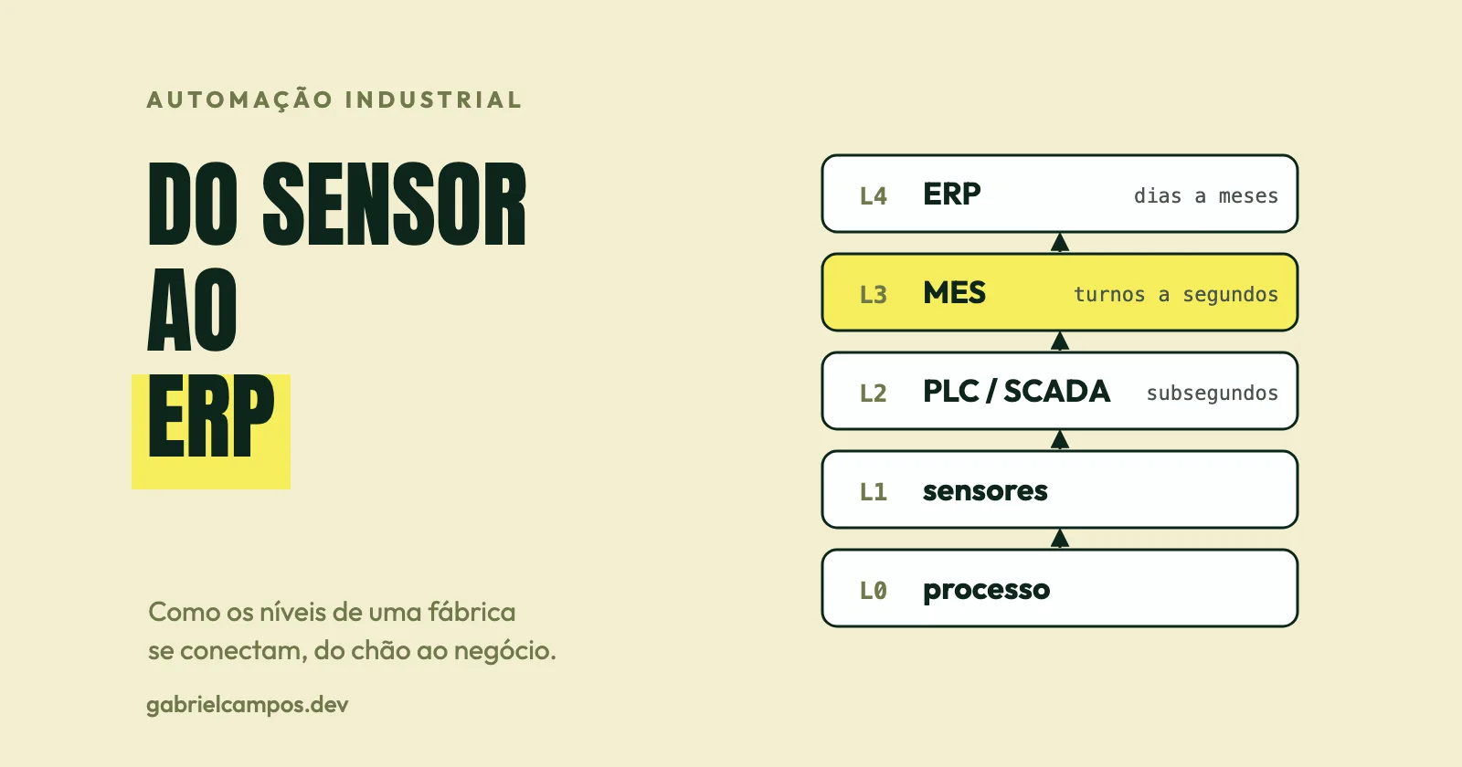
Software Architecture of a Modern Factory: From Sensor to ERP
How sensors, PLCs, SCADA, MES, historians, and ERP fit together, the ISA-95 standard, and the path of production data from the shop floor to enterprise IT.
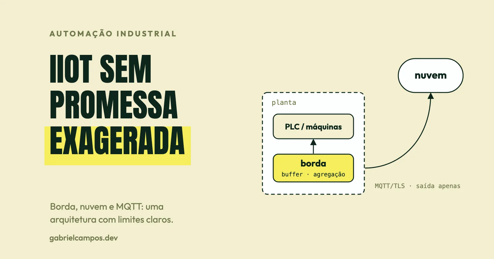
IIoT and Industry 4.0: Architectures with Edge and Cloud
What distinguishes IIoT from IoT, how to design telemetry pipelines across edge and cloud, the role of MQTT and OPC UA, digital twins, predictive maintenance, and real costs.